Small Hollow Concrete Block Masonry
General requirements
When laying small concrete hollow blocks, moisture condition matters. For ordinary concrete small blocks, the preferred condition is their natural moisture content. In hot, dry weather, they may be wetted in advance. Lightweight aggregate concrete small blocks should generally be watered 1 to 2 days ahead of laying. Work should not proceed in rainy conditions, and any block with free water on the surface must not be used.
Masonry work
Small blocks used in wall construction must have reached an age of at least 28 days.
For walls thicker than 190 mm, it is advisable to run guide lines on both the interior and exterior faces of the wall.
Blocks should be laid upside down relative to their production position, meaning the bottom face formed during manufacture should face upward in the wall.
Clay brick or other walling materials must not be mixed into small-block walls. If local infill is necessary, it should be done with matching precast concrete units of suitable size and with a strength grade not lower than C20.
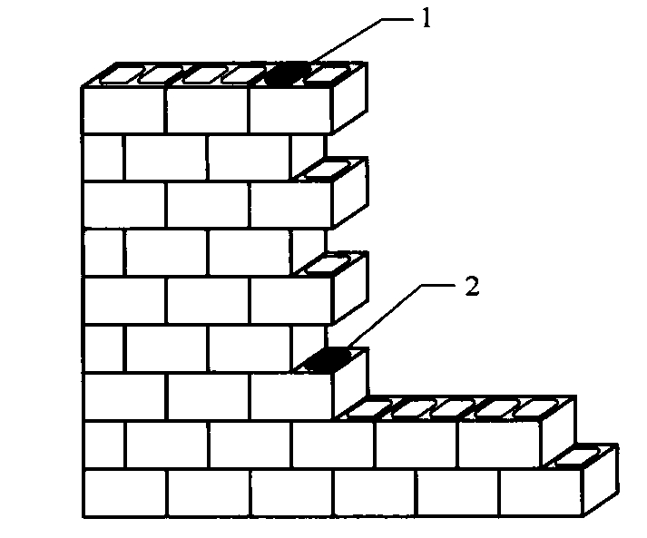
Small-block masonry should be laid with staggered vertical joints and aligned holes. Bonding must satisfy the following:
- For single-row-hole blocks, the lap length should be half the block length.
- For multi-row-hole blocks, the lap length should preferably not be less than one-third of the block length.
- If bonding requirements cannot be met at isolated locations, a φ4 steel mesh should be placed in the horizontal mortar joint at that location, with both ends of the mesh at least 400 mm away from the adjacent vertical joints, or matching auxiliary units should be used instead.
- Continuous vertical joints in walls must not extend through more than two courses of blocks, and free-standing columns must not have continuous vertical joints.
Corners and intersections of walls should be built at the same time. Temporary construction stoppages should be formed as raked joints, and the horizontal projection length of the rake should be at least equal to its height. Straight toothed joints may be left only at temporary construction openings. When these openings are later filled in, the block cores directly above and below the straight joint where overlap occurs must be filled solid with concrete of strength grade not lower than Cb20 or C20.
For ordinary exposed wall surfaces, joints should be pointed promptly using the original mortar. A concave joint is preferred, with a recommended recess depth of 2 mm. For the exposed face of decorative sandwich composite walls, extra pointing mortar should be used; concave round or V-shaped joints are preferred, with a recess depth of about 4 to 5 mm.
Horizontal bed joints and vertical head joints should generally be 10 mm thick, but in no case less than 8 mm or more than 12 mm. Joints must be straight and even, both horizontally and vertically.
Small-block walls should be built using double-row scaffolding or tool-type scaffolding. If scaffold holes must be set in the wall, they may be formed by laying auxiliary-size blocks on edge and using their openings for the scaffold connection. After wall completion, these openings must be filled solid with concrete of strength grade not lower than Cb20 or C20.
Under normal construction conditions, the daily height of small-block masonry should be limited to 1.4 m, or to the height of one scaffolding lift.
Concrete core columns
At locations where concrete core columns are required, the wall should be built with through-hole small blocks that do not have closed bottoms.
When placing concrete into core columns, the following rules apply:
- Debris inside the cores must be removed, and the interior surfaces should be flushed with water and moistened.
- If formwork is used to close the access opening, measures must be taken to prevent grout leakage.
- Concrete for the core column may be placed only after the masonry mortar has reached a strength greater than 1.0 MPa, and each storey should be poured continuously.
- Before placing the core concrete, first place a 50 mm layer of cement mortar without coarse aggregate, using the same mix proportion as the core concrete; then place the concrete. Compaction should be carried out once for about every 500 mm of placed height, or continuously by using an internal vibrator during placing.
- The required concrete quantity for each core column should be calculated in advance, and the pour should be controlled by measured quantity.
- At the junction between a core column and a ring beam, a construction joint may be left 50 mm below the underside of the ring beam.
Quality inspection
Inspection of core columns in small-block masonry should meet these requirements:
- The compactness of the concrete in core columns should be checked by hammer sounding; core drilling or ultrasonic testing may also be used.
- The dimensions and arrangement of core columns at floor levels should be checked storey by storey.
Stone Masonry
General requirements
At corners and intersections, stone masonry should be built simultaneously. If a temporary interruption must be left, it should be formed as a raked joint.
Stone used in beams and slab-type flexural members must be free of cracks. For stone beams, the top and bottom faces should be rough, while the side faces should be even and smooth. For stone slabs, the top and bottom faces should be even and smooth, while the side faces should be rough.
Stone masonry should be laid by the full-bed mortar method. Mortar must be fully packed, and the bonded mortar area on the bearing surface between stones should exceed 80%.
The daily height of stone masonry must not exceed 1.2 m.
When pointing stone masonry joints:
- For flush joints, the joint must be tightly packed, finished flush with the stone face, and trowelled smooth.
- For raised joints, the joint should first be filled level with mortar; after initial set, a second layer of mortar is applied, compacted, and shaped into a raised band 40 mm wide.
- For recessed joints, the joint should be tightly packed and finished about 10 mm back from the stone face, then smoothed.
Rubble stone and dressed stone masonry
Rubble stones used in rubble masonry must be free from weathering, scaling, and cracks. They must not be thin, flat, elongated, or pointed. The stones should be block-shaped, and the middle thickness should preferably be at least 150 mm.
Rubble masonry should preferably be laid in horizontal courses with staggered joints. The lap length must not be less than 80 mm. When bonding the inner and outer wythes, the wall must not be built by standing side stones on the face and filling the middle loosely. The interior must not contain so-called shovel-mouth stones, axe-edge stones, or bridge stones. The first course of rubble masonry, as well as corners, intersections, and openings, should be built with larger, flatter stones.
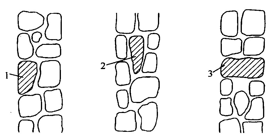
Mortar joints in rubble masonry must be full and dense. Exposed joint thickness should preferably not exceed 40 mm, and stones must not touch one another directly. Larger voids between stones should first be packed with mortar and then tightly wedged with small stone chips. It is not acceptable to place chips first and then pour in mortar, nor to dry-pack stone chips without mortar.
Construction must avoid through joints, dry joints, void joints, and holes.
When laying the first course of a rubble stone foundation, a mortar bed should be spread first over the foundation trench bottom, and each stone should be laid with its broad face downward. In stepped rubble foundations, the stones of the upper step must overlap at least one-half of the lower step, and adjacent steps should be bonded with staggered joints.
Vertical lines and level lines should be used when laying rubble foundations.
Rubble masonry must include bond stones, arranged as follows:
- Bond stones should be distributed evenly and staggered.
- In rubble foundations, one bond stone should preferably be provided every 2 m within the same course.
- In rubble walls, at least one bond stone should be provided for every 0.7 m2 of wall surface, and the spacing within the same course should not exceed 2 m.
- If the foundation width or wall thickness is not greater than 400 mm, the bond stone length should equal the full width or thickness.
- If the width or thickness exceeds 400 mm, two bond stones may be lapped from the inner and outer sides, with a lap length of at least 150 mm; one of the two stones must be at least two-thirds of the foundation width or wall thickness.
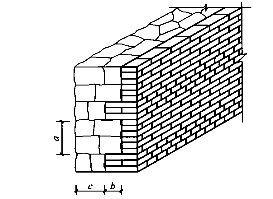
In composite walls combining rubble stone, dressed stone, and solid brick, the stonework and brickwork should be built at the same time. Every 4 to 6 brick courses, 2 to 3 courses of header bricks should be used to tie into the rubble masonry. The interlocking length between rubble stone and solid brick must be greater than 120 mm, and the gap between the two materials must be fully filled with mortar.
Dressed stone walls may be laid in several bond patterns, including alternating header-and-stretcher courses, two stretchers to one header, grouped header-stretcher bonding, and all-stretcher courses.
The first course of a dressed stone wall, and the topmost course at each floor level, should be laid as header courses.
Retaining walls
For rubble stone retaining walls:
- The middle thickness of each rubble stone should preferably be at least 200 mm.
- Every 3 to 4 courses should generally be treated as one lift, and each lift should be levelled once.
- On exposed faces, mortar joint thickness must not exceed 40 mm, and the offset between joints of adjacent lifts must be at least 80 mm.
Dressed stone retaining walls should preferably use alternating headers and stretchers within the same course. If the middle portion is filled with rubble, the header dressed stones must extend at least 200 mm into the rubble portion.
Retaining walls should be built to the designed batter or stepped profile using slope templates or profile guides, and expansion joints and weep holes must be provided. Weep holes are preferably formed by withdrawing tubes or embedding pipes.
Weep holes in retaining walls must be left in accordance with the design. Where the design gives no detailed requirement, construction should follow these rules:
- Weep holes should be arranged uniformly in both the vertical and horizontal directions. Within each 1 m height band of the retaining wall, the horizontal spacing of weep holes must not exceed 2 m.
- The diameter of each weep hole must not be less than 50 mm.
- Between the weep hole and the retained soil, a drainage layer of pebbles or crushed stone must be provided, with length and width each not less than 300 mm and thickness not less than 200 mm.