Overview
After successfully obtaining a PS stream from a Hikvision IPC camera by simulating both a SIP server and a SIP client under GB28181, the next step is to inspect what is actually being pushed over the wire. The goal here is not to explain every field in the protocol stack, but to work through a real capture and identify how the incoming RTP data wraps PS content and, eventually, H.264 video.
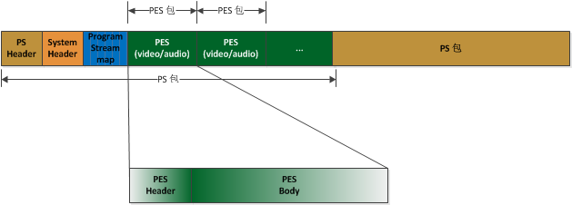
The diagram above shows the GB28181 packaging model. IPC devices that interoperate with a GB28181 platform follow this structure.
What to prepare first
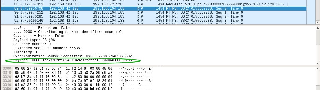
If you are already receiving Hikvision RTP packets, the easiest way to inspect them is with Wireshark. Another option is to work directly with the raw binary payload extracted from Wireshark. In this case, the sample being analyzed is the RTP payload from the first packet returned after requesting the video stream.
Open that binary data in a hex editor or binary viewer and follow the structure from there.
Overall layout of the RTP payload
For the first packet, the structure looks like this:
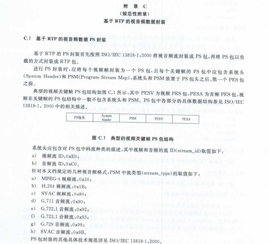
RTP Header + PS Header + PS System Header + PSM + PESV (Header + Payload)
For later packets, the structure is usually simplified to:
RTP Header + PS Header + PESV (Header + Payload)
The RTP header itself is not the main concern here. The focus is on locating the H.264 elementary stream inside the PS data, so some fields that are not immediately useful are skipped.
PS header
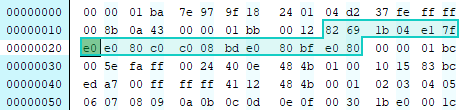
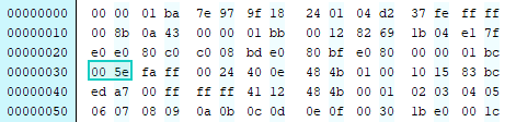
The RTP payload carries PS data. The marker 00 00 01 ba indicates the beginning of a PS packet.
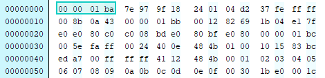
From there, skip 9 bytes for the moment and look at the 10th byte, fe, which in binary is 1111 1110.
Its last three bits are 110, which equals 6 in decimal. That means the next 6 bytes are extension data.
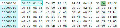
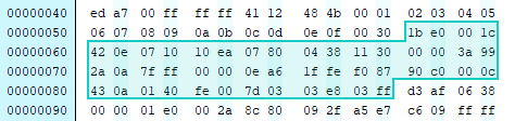
After skipping those 6 bytes, the next start code appears: 00 00 01 bb. That marks the PS System Header.
PS System Header
The System Header appears only in the first packet.
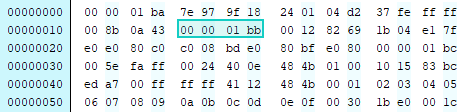
These four bytes indicate the start of the System Header. The next two bytes, 00 12, are the length field. In decimal, that is 18 bytes.
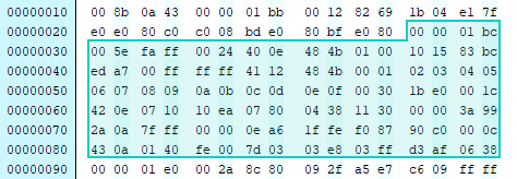
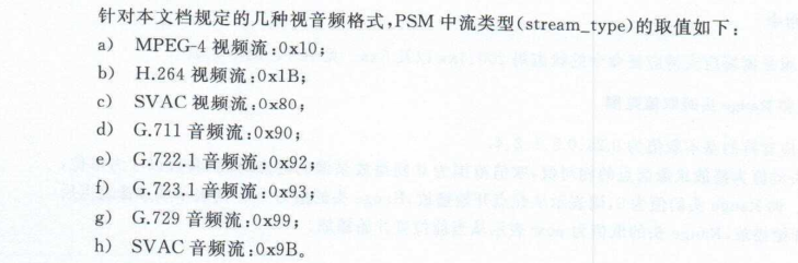
This part is useful because it reveals the stream types present in the PS through system_id values. The layout from the standard document makes the extraction fairly clear.
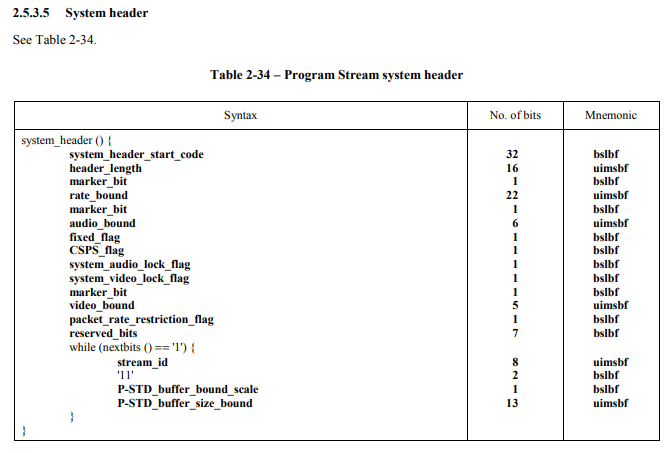
A reference specification for PS formatting is the PDF iso13818-1:2000.pdf.
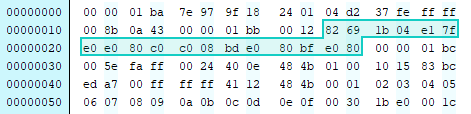
According to that structure, after header_length there are 6 bytes, and then the stream_id field appears.
The system_id here is e0. Comparing that with the GB28181 definition shown earlier, this identifies a video stream.
The System Header then continues in 3-byte cycles. In the next cycle, the system_id value is c0, which indicates audio. Later, bd also appears.
A note from another technical write-up identifies 00 00 01 bd as a Hikvision private stream marker. It can be discarded. If it is removed, the flashing red motion-detection box embedded in the original video is no longer visible.
Likewise, bf has also been described elsewhere as Hikvision private data.
Another useful reference for the PS System Header format is:
http://stnsoft.com/DVD/sys_hdr.html
Program Stream Map (PSM)
Continuing after the System Header, another 00 00 01 appears. This three-byte sequence serves as a separator between sections.
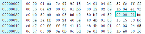
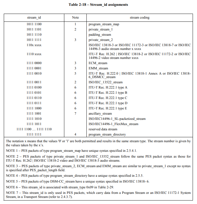
At this point the data type is not yet known, so inspect the following byte: bc, whose binary form is 1011 1100.
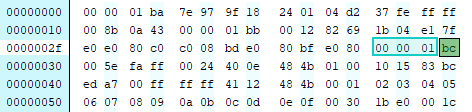
Looking this up in the stream_id table shows that this segment is a program_stream_map, or PSM.
Its detailed structure is as follows:
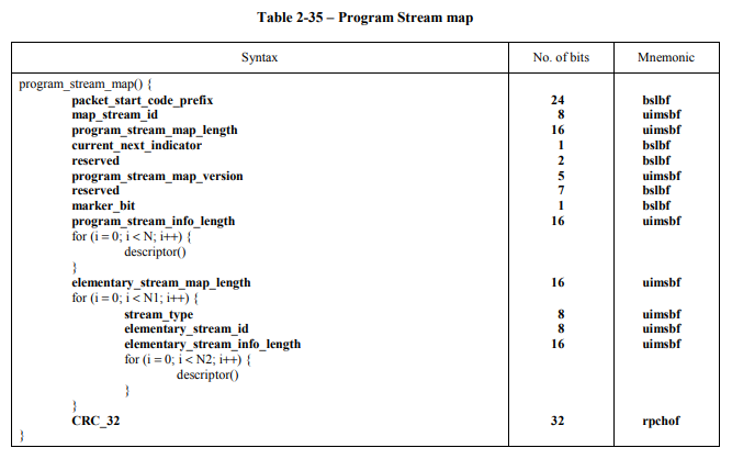
As before, the next two bytes represent the header length. Here the value is 00 5e, which is 94 in decimal.
So the next 94 bytes belong to the PSM section. This is where the exact codec type of the video stream can be determined.
Following the PSM structure: after 00 5e, skip the two fixed fields that come next and you reach program_stream_info_length, a 2-byte field. Its value is 00 24, meaning the following descriptors take up 36 bytes.
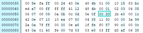
Skip those 36 bytes and the next value, 00 30, is element_stream_map_length. That is 48 bytes, which means the next 48 bytes describe the elementary streams.
The first loop over this elementary stream description starts with a stream_type value of 1b.
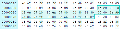
Under GB28181, 1b corresponds to H.264. The following e0 shows that it is a video stream.
The next field, 00 1c, means the following description occupies 28 bytes.
The next loop works the same way. The values 90 and c0 indicate a G.711 audio stream.
After two such loops, the total consumed bytes match the element_stream_map_length of 48, so the loop ends. The next 4 bytes are CRC_32.
PES packets: header and payload
After the PSM comes PES data. A PES packet has two parts:
- Header: descriptive metadata
- Payload: the raw elementary stream data
There may be multiple PES packets in the same PS packet.
PES header
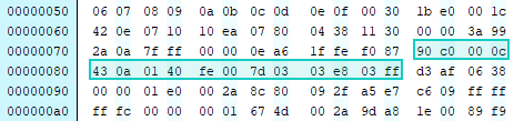
A PES packet also begins with 00 00 01. The next byte determines the type. In this capture it is e0, binary 1110 0000, which again indicates a video stream.
The following 00 2a is the length, meaning the remaining data in this PES packet is 42 bytes long.
From here the packet can be parsed using the PES structure definition. When the stream_id is not one of the special exempted types, the rest of the PES header fields need to be interpreted.
At the start there is a fixed 2-bit value 10. In the capture, this is part of 8c (1000 1100). After combining the relevant bits and moving past them, the next notable byte is 80, which in binary corresponds to PTS_DTS_flags = 10.
The meaning is straightforward:
10: PTS is present in the PES header11: both PTS and DTS are present00: neither PTS nor DTS is present01: invalid
So in this case the PES header contains PTS but not DTS. These timestamps are primarily used for audio/video synchronization.
PES itself is packetized ES, a structure used to transport elementary streams. In other words, ES data is grouped, packetized, and given header information; PES is the first layer of packaging above the raw ES.
- PTS: Presentation Time Stamp, the time when the display unit should appear at the system target decoder
- DTS: Decoding Time Stamp, the time when the access unit should be removed from the decoder buffer for decoding
PTS and DTS are essential for synchronization and for preventing decoder buffer overflow or underflow. Every I/P/B frame header may carry these values.
Another field worth watching is PES_header_data_length. It is located after the 2-byte PES packet length and indicates how many bytes belong to the optional PES header area.
In this capture its value is 09, meaning 9 bytes follow as PES header data. That is enough to split the PES header from the actual payload, even if the other fields are ignored.
The PES screenshots in the sample all begin with 00 00 01 e0, and there are multiple PES packets. One of them is much larger: its length field is ff c6, which equals 65478 bytes. Looking at the second byte after the length field, 00 (0000 0000 in binary), you can tell that PTS_DTS_flags is 0 for this PES packet, so neither PTS nor DTS is present.
The next byte is 05, meaning PES_header_data_length is 5 and the header data section is 5 bytes long.
PES body: the H.264 payload
Immediately after the PES header comes the payload. The sequence 00 00 00 01 marks the beginning of the H.264 data.
Looking at the PES packets in this example, there are four of them, and their payloads begin respectively with:
67680665
Under H.264 encapsulation rules, these mean:
67: SPS68: PPS06: SEI message65: I-frame
In the first PS packet received from the Hikvision device, the total data from the start of the packet up through the I-frame is clearly nowhere near 1400 bytes. But the last PES packet declares a length of 65478 bytes, which strongly suggests that the I-frame is too large to fit in a single network packet and has therefore been fragmented.
The packet being analyzed here has a PS payload size of at most 1400 bytes.
For packet 00:
pack 00:1400 - 245 = 1155
So from 00 00 00 01 to the end of that packet, there are 1155 bytes of H.264 data.
Then:
65478 - 8 = 65470 - 1155 = 64315
Here ff c6 is the PES packet length. Subtract the 8-byte header to get the number of video bytes beginning at 00 00 00 01, then subtract the 1155 bytes already contained in the first fragment. That leaves 64315 bytes in subsequent packets.
Because many of the following packets are just continuations of the same I-frame, they contain no additional PS or PES headers. In those packets, the full 1400 bytes are H.264 payload.
64315 / 1400 = 45.939...
So the end of this I-frame should appear in approximately sequence packet 46. Checking packet 46 confirms it: near the end of the packet, the next video frame start marker 00 00 01 e0 appears.
What this reveals about Hikvision PS over GB28181
By stepping through the structure of a real Hikvision PS stream, the layering becomes clear enough for practical parsing even without exhaustively decoding every parameter.
The RTP payload carries a PS packet. That PS packet may contain:
- a PS Header
- a System Header
- a PSM
- one or more PES packets
Under GB28181 notation, video and audio PES may be referred to as PESV and PESA. Once the PS structure is understood, a parser can walk through these sections and extract the elementary stream data—such as H.264—from the PES payload for later decoding.