Rainfall analysis and the storm intensity formula
Storm sewer design starts with a small set of interrelated variables. The key ones are:
- rainfall depth
- rainfall area and drainage area
- runoff and runoff coefficient
- time of concentration, including surface inlet time $t_1$ and pipe travel time $t_2$
- rainfall duration $t$
- storm intensity
- rainfall frequency and return period
Rainfall area vs. drainage area
The rainfall area is the total area covered by a storm. The drainage area is the area whose runoff is collected by the storm sewer system. The rainfall area is larger than the drainage area.
Storm intensity
Storm intensity is expressed as:
$$ i=\frac{H}{t}(mm/min) $$
In practice, the unit $mm/min$ is inconvenient for engineering calculations, so it is commonly converted:
$$ \frac{mm}{min}=\frac{10^{-3}m}{60s}=\frac{10^{-3}m^3}{60s×m^2}=\frac{10^{-3}m^3}{60s×10^{-4}×hm^2}=\frac{10^{-3}×10^3L}{60s×10^{-4}×hm^2}=\frac{10^4}{60}=167[L/(s\cdot hm^2)] $$
This leads to another parameter often used in place of $i$:
$$ q=167i $$
So in design work, it is essential to check whether the provided value is $i$ or $q$.
Determining design flow in storm sewers
The design discharge is commonly calculated by:
$$ Q_s=\varPsi qF $$
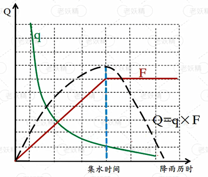
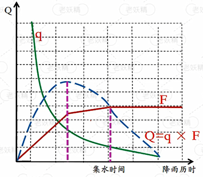
Here, as rainfall begins, storm intensity $q$ decreases over time, while the effective drainage area $F$ contributing runoff to the design section increases. Under the limiting intensity concept, the increase in contributing area is assumed to outweigh the decrease in rainfall intensity, so the stormwater flow $Q$ keeps rising during this stage.
Once rainfall duration equals the time of concentration—that is, the moment runoff from the most remote point just reaches the design section—the contributing area has reached its maximum. After that, $F$ no longer increases. Since $q$ continues to decrease, the discharge also begins to fall.
This gives the classic conclusion:
Stormwater discharge reaches its maximum when rainfall duration equals the time of concentration.
A hidden assumption behind this equation is that the contributing drainage area increases at a constant rate as runoff travel time grows.
Where the usual assumption breaks down
That assumption does not always hold.
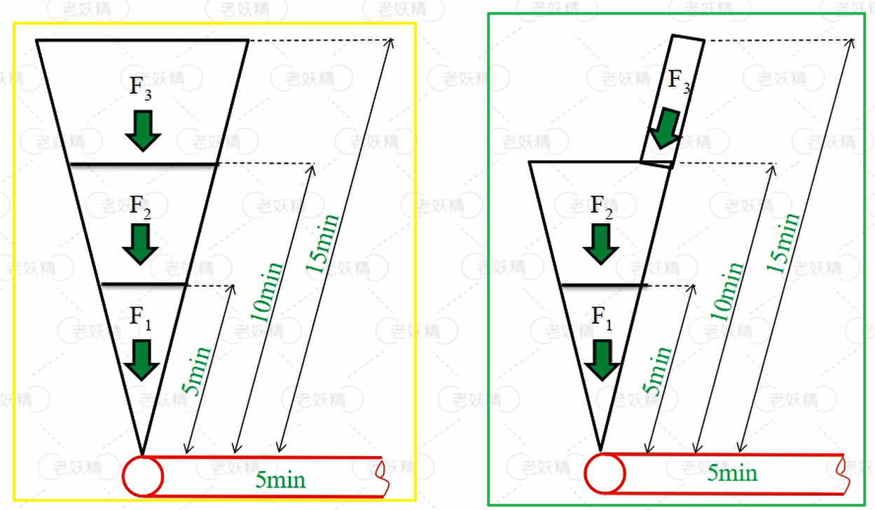
If the contributing area does not increase uniformly with rainfall duration, the simple area-based peak estimate can become inaccurate. For example, if a zone like $F_3$ is very small but takes extra time to contribute runoff, then while waiting for that area to arrive, the peak flow generated earlier from $F_1$ and $F_2$ may already have passed the section. In other words, the runoff from all subareas does not necessarily arrive together at one common peak.
In such cases, the computed discharge for the abnormal case is actually smaller than what the idealized case would suggest. A special-area approach is then required.
Two calculation approaches
There are two main methods:
- area method
- flow superposition method
Area method
This method directly sums all contributing drainage areas and uses the rainfall intensity corresponding to the concentration time of the most remote point.
One practical warning: do not assume that the physically farthest drainage area automatically has the longest concentration time. Hydraulic travel conditions matter more than map distance alone.
Flow superposition method
This method adds:
- the flow conveyed from upstream pipe reaches, and
- the local runoff generated within the reach being designed.
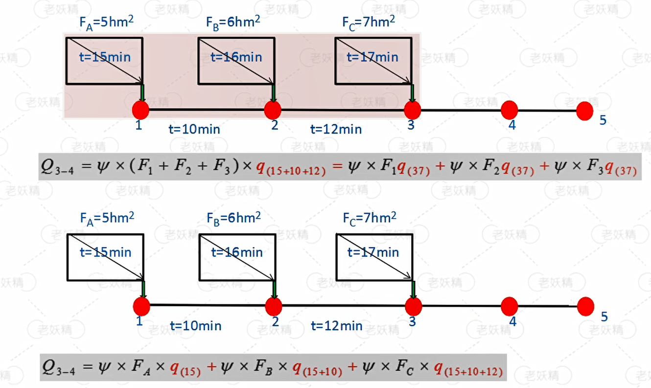
The area method is straightforward and rough, so it is suitable for preliminary planning. The flow superposition method is more refined and is better suited to detailed design and construction drawings.
Why the reduction coefficient $m$ was used
As stormwater flows through a sewer, the pipe is not flowing full at every moment. However, the velocity used in calculation is often the full-flow velocity. That means the actual flow velocity in the pipe is lower than the calculated one, so the real travel time is longer than the computed value.
A reduction coefficient $m$ was therefore introduced to make the travel time estimate more realistic.
In recent years, however, this coefficient has gradually fallen out of use. The main reason is to increase the safety margin of storm sewer networks. Although the maximum flow in every pipe reach cannot occur simultaneously, removing the reduction coefficient increases the design discharge and therefore leads to larger pipe diameters, giving the system a higher safety capacity.
Special drainage areas and their flow calculation
These cases are characterized by the fact that the drainage area does not increase uniformly with runoff travel time. As a result, the maximum pipe flow may occur before the entire drainage area is contributing runoff.
Typical situations include:
- large variation in ground slope across the drainage area;
- significant differences in runoff coefficients among subareas;
- highly irregular drainage boundaries, including distorted area growth or convergence of several separate areas located far from one another.
Storm sewer system layout and design principles
Trunk sewer alignment
- Where terrain slopes vary greatly, the storm trunk sewer should preferably be laid along low ground or valley lines.
- On flat terrain, the trunk sewer should preferably be arranged near the middle of the drainage basin so branch sewers can connect easily and the area served by gravity drainage can be expanded as much as possible.
Outfall arrangement
- When the sewer discharges into a pond or a small river, a distributed outfall layout is generally preferable. It allows nearby discharge, shorter pipe runs, and smaller pipe diameters.
- If river water levels fluctuate greatly and there is a large elevation difference between the sewer outfall and the normal water level, the outfall structure becomes more complicated and more expensive. In that situation, too many outlets should be avoided, and a centralized outfall arrangement is preferable.
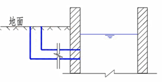
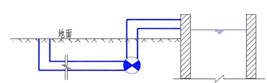
- On flat terrain where the average ground elevation is lower than the river’s normal water level, storm sewer outlets should be concentrated appropriately. A stormwater pumping station should be provided before discharge, and a regulating basin should preferably be installed upstream of the pump station to reduce both construction cost and operating cost.
Catch basin placement at road intersections
The basic rule is simple:
Let water leave the intersection, but do not let it enter.
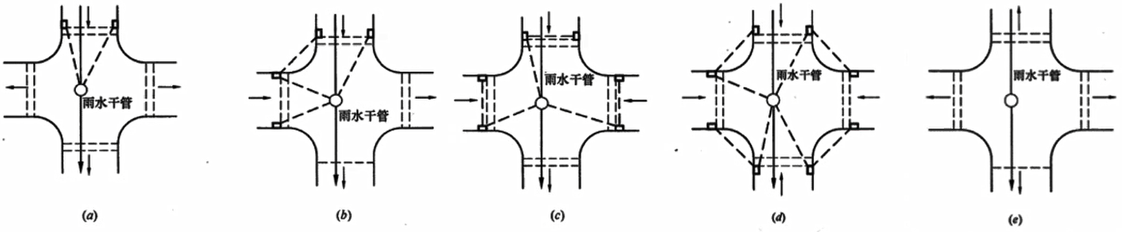
If surface runoff is flowing toward a road intersection, catch basins must be installed before the flow enters the intersection so the water is intercepted in advance. If runoff is flowing out of the intersection, additional catch basins there are not necessary.